In structural engineering, the base plate connection is the critical interface where the superstructure (the steel frame) meets the substructure (the concrete foundation). Its primary purpose is to transfer loads—axial, shear, and moment—from the relatively small cross-section of a steel column to the much larger surface area of a concrete pedestal.
Based on the technical diagram provided, here is an in-depth evaluation of the components and their functional performance.
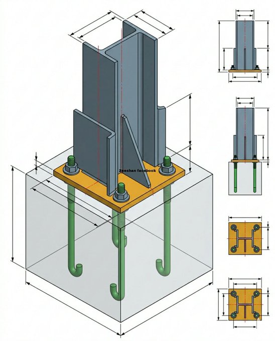
1. The Anatomy of the Connection
The Steel Column (H-Section)
The image features a Universal Column (UC) or H-beam. This profile is preferred for vertical members because it provides excellent resistance to compressive loads and bending in both axes. In this assembly, the column is welded directly to the base plate, usually via fillet or butt welds.
The Base Plate
The base plate serves as a load distributor. Because steel has a much higher compressive strength than concrete, placing a raw steel column directly onto concrete would cause the concrete to crush (punching shear). The plate increases the contact area, ensuring the bearing pressure remains within the allowable limits of the concrete grade (e.g., Class 25/30).
Anchor Bolts (J-Bolts)
The diagram shows four heavy-duty J-bolts embedded deep within the concrete foundation.
Function: They resist "uplift" forces caused by wind or seismic activity and hold the column in place during the construction phase.
Design Fact: The "J" hook at the bottom provides mechanical anchorage, preventing the bolt from pulling out of the hardened concrete under tension.
Stiffeners (Gusset Plates)
Perhaps the most notable feature of this specific design is the inclusion of vertical stiffeners.
Evaluation: The presence of these triangular and rectangular plates suggests this is a moment-resisting connection.
Purpose: Stiffeners prevent the base plate from bending or "cupping" under heavy loads. They reinforce the connection between the column flanges and the plate, significantly increasing the rigidity of the joint.
2. Technical Evaluation of Load Transfer
This connection is designed to handle three primary types of stress:
Axial Compression: The weight of the building travels down the column and is spread across the foundation via the base plate.
Shear Forces: Horizontal forces (like wind hitting the side of a warehouse) try to slide the column off the foundation. These are resisted by the friction between the plate and the concrete, and the bearing of the anchor bolts.
Moment (Bending): If the building tries to tilt, one side of the base plate is pushed down (compression) while the other is pulled up (tension). The stiffeners and anchor bolts work together to keep the column perfectly vertical.
3. Critical Installation Facts for the Kenyan Context
While the diagram presents an idealized model, successful implementation on a Kenyan construction site requires attention to several factual requirements:
The Grout Gap: In practice, a gap of 25mm to 50mm is usually left between the concrete and the base plate. This is filled with non-shrink high-strength grout after the column is leveled using leveling nuts. This ensures 100% contact between the plate and the foundation.
Material Specification: In Kenya, structural steel typically follows British Standards (BS 5950) or Eurocodes. The plate is usually S275 or S355 grade steel, while the bolts must be high-tensile to prevent shearing.
Corrosion Protection: Since the base plate is near the ground, it is highly susceptible to moisture. Facts dictate that these components should be either hot-dip galvanized or coated with zinc-rich epoxy primers to prevent rust, which can weaken the connection over time.
4. Evaluation Summary
Strengths of this Design:
High Rigidity: The use of stiffeners makes this suitable for high-rise steel buildings or heavy industrial warehouses with overhead cranes.
Stability: The four-bolt configuration provides excellent stability during the "erection" phase of construction.
Potential Red Flags:
Welding Complexity: The high number of stiffeners requires extensive welding. If these welds are not tested (e.g., via Ultrasonic Testing), they become the "weak link" where the connection could fail.
Congestion: In small concrete pedestals, four large J-bolts can create reinforcement congestion, making it difficult to pour concrete properly without "honeycombing."
Conclusion
The steel column base plate is the literal "footing" of a modern steel structure. As seen in the diagram, a well-engineered connection uses a combination of surface area (the plate), depth (the bolts), and reinforcement (stiffeners) to ensure that the building remains standing even under extreme conditions. For any Kenyan developer, ensuring these components meet the engineer's specifications is non-negotiable for structural longevity.
Expert Guide: This diagram highlights a very robust, "fixed" connection. Are you planning an industrial build where you need to know more about the specific concrete grades required for these pedestals, or are you interested in the cost difference between "pinned" and "fixed" steel connections?


Comments
Post a Comment